Digitial PPM Receiver


- Details
- Published on Friday, 20 September 2013 03:53
- Written by Gordon Anderson
- Hits: 25712
![]()
The PulseStar receiver is designed specially for the MicroStar 2000 transmitter. This receiver exploits the special features of the MicroStar, but will work with any PPM transmitter. The PulseStar uses state-of-the-art microcontroller technology toenable unique features never before offered in a PPM receiver.
Typical PPM receivers use a simple shift register as a decoder. This type of design is very susceptible to interference and glitching. I’m sure you have experienced this problem especially when you run an electric drill next to your radio and see the servos jitter about. The PulseStar uses a microcontroller to record the data from the detector and inspect the pulse train. Several checks are performed to insure the data frame is valid. Only valid data frames are decoded and sent to the servos. If a bad frame is detected, the PulseStar will throw it away and use the last valid frame. If no valid frames are detected for a user-defined amount of time, the PulseStar will send the servos to there fail safe position.
The microcontroller allows several unique features to be built into the receiver. A list of some of these features are listed below.
Features:
- PPM
- Dual conversion
- Narrow band
- 8 channels
- Synthesized
- Microprocessor controlled decoder
- Battery voltage monitor
- Signal strength monitor
- Servo reversal
- Active high or active low servo output. (Use your old Proline servos!)
- Channel assignment/Channel order
- Mixing
- V tail
- Elevon
- Position hold
- Fail-safe
- Glitch proof operation/intelligent decoder
- Data logger
- RS232 Computer interface
- In circuit programmable
- Size 2.1” x 1.45” x .5”
- 50MHz, and 72MHz bands
- 4 or 5 cell batter operation
- Option connector
- Automatic channel selection
The PulseStar’s computer interface allows you to configure the receiver using your PC. The configuration information is saved in non-volatile memory. The PulseStar records status parameters during a flight. These parameters include the number of invalid frames, the number of times fail safe was entered, average signal strength, etc. These parameters can be downloaded to a PC for analysis after each flight. You can even record the signal strength as a function of time to allow you to evaluate your flying site.
20 pin option connector is included to allow for future optional accessories as well as providing a easy way to set the operating channel. This option connector is a unique feature of the PulseStar and will allow development of the following accessories:
Option connector allows:
- Channel selection
- Engine rpm/governor
- Leveling system using optical sensors
- Leveling system using accelerometers
- Status LED using ultra bright LEDs
- Air speed monitoring/stall control
- Parallel interface to fully automated flight control system.
The PulseStar is the next generation in PPM receivers!
Circuit description:
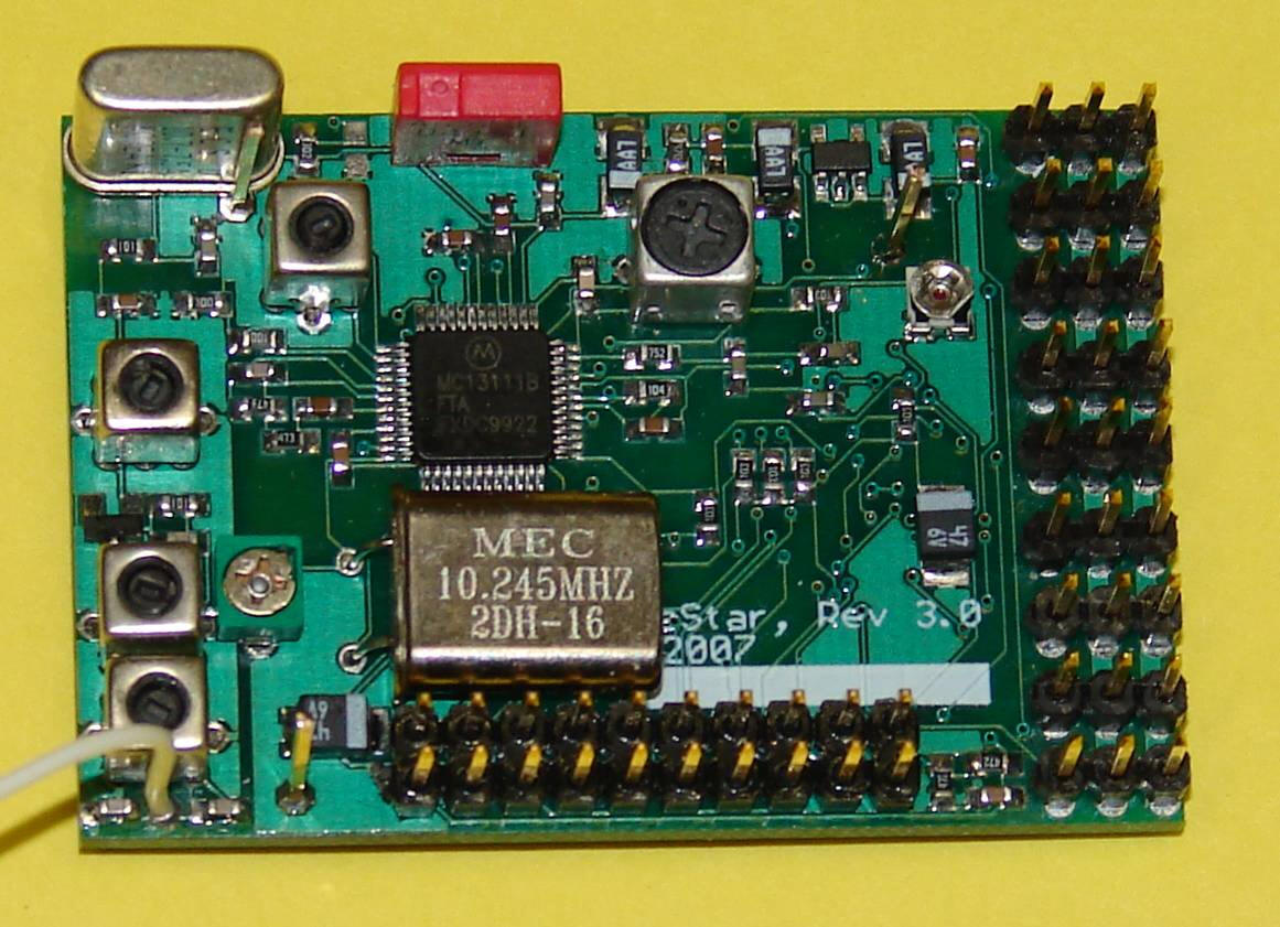
PulseStar circuit is very simple. The heart of the receiver is the Motorola MC13111 Universal Narrowband FM receiver IC. This chip contains the entire synthesized receiver. A FET RF pre-amp precedes the MC13111 and an Atmel mega16 microcontroller is used to configure the MS13111 and decode the pulse stream thus producing the servo control pulses.
A 4-volt regulator is used to provide regulated voltages for the microcontroller and the receiver electronics.
The Atmel microcontroller is a very capable device with analog inputs as well as digital IO. The analog inputs allow monitoring of DC battery voltage and RF signal strength. Addition analog input channels are connected to the option connector and will be used for future monitoring and control functions. Decoding of the input PPM pulse stream is performed in software in the Atmel microcontroller. Software algorithms have been developed to validate each input data frame and only send information to the servos when valid data frames are received. Position hold and fail-save functions are also implemented in the Atmel controller.
The microcontroller has 512 bytes of ram which are used for variable storage as well as memory for data logging. Information like signal strength or external analog signals can be logged. 512 bytes of non-volatile storage are also used to maintain setup parameters.
The Atmel microcontroller can be programmed in circuit, the program is saved in flash memory. This makes it easy to update the firmware in the PulseStar when new versions become available. A simple download cable can be built for less that $10 in parts.
December31, 2007 update
I have finished the design of revision 3.0 of the receiver. This is the 4th prototype design that I have built This time I have ordered 48 PC boards because I felt the design was pretty sound after the previous prototypes. I have devoted a lot of time to the PulseStar receiver over the last few months and I feel its ready for flight testing. I hope to have the first flight test in early January. I am sure there are additional developments that are needed and bugs to be found but the design is very near complete. I will be selling PC boards and boards with a programmed microcontroller and receiver chip installed, what I call a short kit. Kees will be selling full kits. I expect the kits to be available in January of 2008.
Please remember this is a hobby for me and I am not a manufacture. I design and build these projects for my own education and I share these results with other like minded individuals. So build and use my projects at your own risk!